CNC Milling vs Lathe Controller: Complete Architecture & Selection Guide
Selecting the ideal numerical control architecture is a foundational decision in modern manufacturing and machine tool retrofitting. While both CNC milling and CNC lathe controllers process ISO G-code instructions to orchestrate precise motor movements, their underlying control algorithms, hardware interfaces, axis handling, and real-time processing capabilities are fundamentally different.
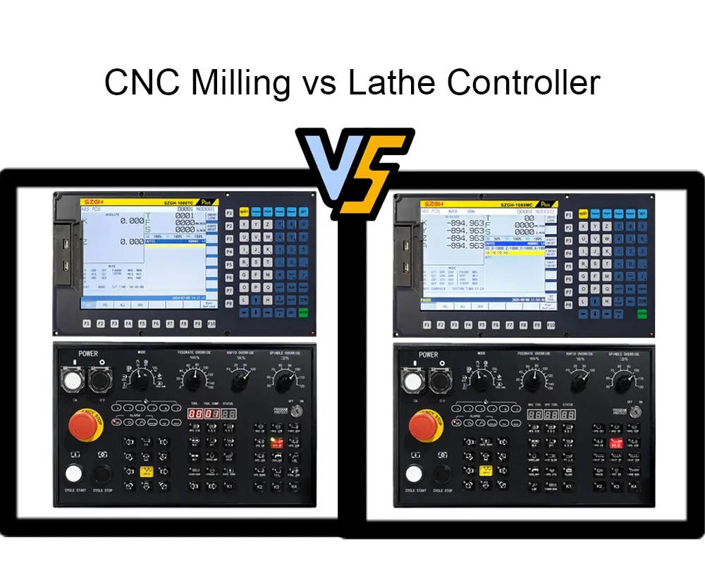
Deploying a mismatched controller—such as adapting a general-purpose milling system to a specialized turning machine—often leads to operational inefficiencies, complex custom programming workarounds, and reduced surface finish quality. This comprehensive guide breaks down the core structural differences between milling and lathe CNC controllers to help system integrators, machine builders, and factory managers make informed technical selections.
1. Fundamental Motion & Kinematic Differences
The architectural divergence between turning and milling controllers stems directly from their mechanical kinematics and tool-workpiece interaction.
CNC Lathe Kinematics
In turning operations, the primary cutting motion is provided by the rotating workpiece held in a chuck or collet. The cutting tool remains stationary relative to spindle rotation and moves linearly along predefined coordinates:
- Z-Axis: Parallel to the spindle center line (longitudinal feed).
- X-Axis: Perpendicular to the spindle center line (cross feed, controlling diameter).
- C-Axis / Y-Axis: Integrated in advanced live-tooling lathes for radial contouring and off-center drilling.
Because turning primarily produces rotationally symmetrical components (shafts, bushings, threads), the controller's motion engine is optimized for 2D plane interpolation (X-Z) with high coordinate precision and diameter-to-radius automatic scaling.
CNC Milling Kinematics
In contrast, milling operations utilize a high-speed rotating tool while the workpiece is secured on a table that translates along multiple orthogonal paths:
- X, Y, Z Axes: Linear coordinates creating 3D spatial motion paths.
- A, B, C Axes: Rotary axes tilting the spindle or rotating the table for 4-axis and 5-axis continuous machining.
The control system must continuously perform complex multi-axis vector transformations and coordinate system rotations (such as RTCP - Rotary Tool Center Point control) to maintain precise feed rates at the tool tip across sculpted surfaces.
2. Controller Architecture & Hardware Specifications
To support different physical machine setups, the embedded hardware, processor allocations, and I/O maps vary between milling and turning control units.
Feature / Dimension | CNC Lathe Controller | CNC Milling Controller |
Primary Motion Type | Workpiece rotates; tools move linearly | Tool rotates; workpiece/table moves across axes |
Standard Axis Channels | 2 to 4 Axes (X, Z, C, plus Y for live tools) | 3 to 6 Axes (X, Y, Z, A, B, C) |
Interpolation Modes | Linear, Circular (X-Z plane), Threading | Linear, 3D Circular, Helical, Spline/NURBS |
Look-Ahead Buffer | Standard (20–100 blocks) | High-Speed Advanced (300–1000+ blocks) |
Spindle Integration | Servo Spindle / Encoder Feedback for Threading | High-RPM Vector Drive / HSK Spindle Control |
Tool Indexing | Fast Turret Logic (4, 8, 12 stations) | Automatic Tool Changer (ATC - Carousel/Chain) |
Programming Focus | Diameter/Radius toggle, Thread Cycles (G71, G76) | 3D Cutter Compensation, Canned Drilling (G81-G89) |
3. Motion Control Algorithms & Real-Time Processing
The software kernel within a CNC unit dictates how G-code commands are translated into motion pulses for digital servo drives.
Advanced Look-Ahead and Velocity Profiling
Milling controllers require massive look-ahead buffers (often processing 300 to 1,000+ blocks ahead) and S-curve acceleration/deceleration algorithms. When executing high-speed mold machining or 3D surface contours, the G-code consists of thousands of microscopic linear segments (G01). The controller must calculate speed transitions across these points to prevent tool chatter, mechanical shock, and surface gouging.
Lathe controllers, while requiring smooth acceleration for precise turning, deal with longer continuous passes (e.g., facing, turning a long shaft). Look-ahead requirements are lower, but real-time processing prioritizes exact spindle-axis synchronization.
Spindle Synchronization for Threading Operations
A defining capability of a lathe controller is thread cutting (G76, G32). The system must lock the Z-axis feed directly to the encoder signal coming from the main spindle:
- The feed rate per revolution ($F$) must strictly match the thread pitch ($P$).
- Any spindle speed fluctuation under load must instantly adjust Z-axis motion to prevent thread pitch errors or ruined workpieces.
- Milling controllers generally use the spindle as an independent speed axis, only requiring rigid synchronization during specialized canned cycles like rigid tapping (G84).
4. Programming Logic, G-Code Sets & Tool Management
While both systems adhere to RS-274D / ISO 6983 G-code standards, the default macro calls and canned cycles differ significantly between lathe and milling configurations.
Canned Cycles and Operator Efficiency
- Lathe Canned Cycles: Lathe controllers feature integrated cycles for rapid material removal. Codes like G71 (Stock Removal in Turning), G72 (Facing Cycle), and G76 (Multiple Threading Cycle) allow operators to define a finished part profile with a few lines of code. The controller automatically generates the roughing passes and tool retractions.
- Milling Canned Cycles: Milling systems feature extensive drilling, boring, and tapping routines (G81 through G89), along with pocket milling and mirror/rotation functions (G68/G69).
Tool Offsets and Compensation Architecture
- Tool Nose Radius Compensation (G41/G42): Lathe controllers compensate for the small radius on the tip of a turning insert. The system calculates tool vector shifts based on the tool tip direction code (quadrant 1–9) to prevent dimensional errors on chamfers and radii.
- Cutter Radius Compensation (G41/G42): Milling controllers adjust the tool center path relative to the programmed contour by the exact radius of the milling cutter, accounting for tool regrinds or diameter variations.
5. Industrial Application Scenarios & Selection Checklist
Choosing between a dedicated lathe controller, a milling controller, or a hybrid multi-axis unit depends on part geometry, production volume, and machine layout.
+------------------------------------+----------------------------------------------+
Checklist for System Integration:
1. Determine the Primary Axis Count: If your machine operates with $X$, $Z$, and a single turning spindle, select a specialized lathe control unit. Adding $Y$ and $C$ axes for cross-milling requires a dedicated mill-turn controller.
2. Evaluate Servo Drive Protocols: Ensure the controller supports your drive communication preferences—whether pulse/direction interfaces for cost-effective step/servo setups, or high-speed fieldbus interfaces (such as EtherCAT) for multi-axis synchronization.
3. Assess Operator Familiarity: Operator efficiency increases when the control interface matches industry-standard G-code syntax, panel layouts, and quick-setting tool offset screens.
4. To explore engineered solutions for high-precision turning automation, retrofits, or multi-axis turning machinery, learn more about our industrial-grade 4-Axis CNC Lathe Controller Systems designed for maximum stability, fast commissioning, and seamless servo drive integration.
6. Conclusion
While both CNC milling and lathe controllers rely on standard G-code input to execute automated machining, their hardware design, firmware logic, and internal motion algorithms reflect fundamentally different machining philosophies.
l CNC Lathe Controllers specialize in 2D plane coordination (X-Z), diameter/radius toggle logic, fast tool turret indexing, and real-time spindle-axis synchronization critical for precise threading operations.
l CNC Milling Controllers prioritize continuous multi-axis interpolation (3 to 5 axes), advanced look-ahead buffers for high-speed 3D surface machining, complex cutter compensation, and flexible canned drilling or pocketing cycles.
Selecting the correct control architecture ensures maximum part accuracy, eliminates unnecessary programming workarounds, and reduces operator setup time. For retrofits, new machine builds, or automated cell integration, choosing a control platform engineered specifically for your primary machining kinematics is essential for long-term production efficiency.
Upgrade Your Production Line with SZGH Control Solutions
Looking for high-performance CNC lathe controllers, servo drives, or custom automation integration for your factory? Our engineering experts provide tailored product selection, technical consulting, and competitive factory-direct pricing. [Contact the SZGH Engineering Team Today] or [Request a Free Instant Quote] to discuss your specific machinery requirements and boost your manufacturing precision!
7. Frequently Asked Questions (FAQ)
Q1: Can a CNC milling controller be adapted to run a 2-axis CNC lathe machine?
A: While technically possible by remapping the X and Z outputs and disabling the Y-axis channel, it is inefficient. Milling controllers lack built-in turning cycles (such as G71 roughing or G76 threading) and default to radius-based programming rather than diameter inputs. This increases CAM post-processor complexity and operator setup time.
Q2: What is the main operational advantage of a 4-axis lathe controller over a standard 2-axis setup?
A: A 4-axis lathe system (controlling X, Z, C, and Y or A axes) supports live tooling. This allows the machine to perform cross-milling, off-center drilling, keyway slotting, and tapping in a single clamping setup—eliminating the need to transfer workpieces to a secondary milling machine.
Q3: How does spindle feedback differ between milling and lathe operations?
A: Milling spindles primarily require velocity feedback to maintain constant surface speed under variable load. Lathe spindles require high-resolution optical encoder feedback synchronized with axis drives to perform precision thread tracking and exact spindle positioning (C-axis mode).